Design of a Cross flow Heat Exchanger
Do you need Design of a Cross flow Heat Exchanger Analysis Assignment Answers? Our online assignment help you to complete your work. We make sure to our 100+ PhD Experts provide plagiarism free assignments with the best quality. If you want Design of a Cross flow Heat Exchanger Analysis Assignment Answers, then connect to our online assignment writing help services.

Assignment Details:
- Topic : Heat Exchangers
- Document Type : Assignment help (any type)
- Subject : Engineering /CDR
The purpose of this assignment is to design a cross flow heat exchanger to transfer as much heat as possible between flow of heating oil and a flow of air and its purpose is to allow students to investigate the relationship between heat exchanger duty, flow, geometry and materials.
The cross flow heat exchanger is to comprise a single pass of tubes, information on materials available, recommended heat transfer correlations and heat exchanger effectiveness relationships are provided.
For set inlet temperatures and mass flow rates of two fluids and available materials, students should propose an arrangement that the best heat recovery for a given frontal area (frontal area is defined as the cross sectional area of the channel/duct that the heat exchanger will fit).
As the actual optimisation of a heat exchanger would require many iterations, students should test a number of combinations of tube size, fin size, material type etc, however the marking of this assignment will judge the degree of student enquiry.
The proposed design should also take into account the cost of the final arrangement.
(The use of correlations and methods covered in course Heat Exchangers and Heat Transfer is for illustration only as the design of an actual heat exchanger would be more complex. In such an arrangement a multi-pass exchanger would be specified.)
Part A (80%)
Provide a final design for a cross flow heat exchanger that recovers the maximum amount of heat for the given specification. Students should include fouling factors that are appropriate for the fluids and context.
The analysis must include any assumptions made and evidence that a number of different combinations of materials, tubes and fins have been investigated (include any references cited).
Provide sample calculations for one design, all other designs can be presented in tabular or graphical form.
Justify any final design recommended.
Part B (20%)
For the chosen design, estimate its performance if the flow rate of the both fluids are reduced by 25%. Supporting calculations must be presented.
Specification
| Gas Side | Air |
| Inlet temperature | 22oC |
| Flow Rate | 10.036 kg/s |
| Fluid Properties | Standard properties
Rogers and Mayhew Tables for dry air can be used (supplied) |
| Maximum gas side velocity | 3 m/s |
| Fluid Side | Heat transfer Oil, Shell-Thermia-B-HTF |
| Inlet temperature | 180oC |
| Flow Rate | 8.705 kg/s |
| Fluid Properties | See property table provided |
| Maximum fluid side velocity | 2 m/s |
| Cross Flow Heat Exchanger | Tubular construction, single pass |
| Frontal area (width x height) | 4 m2 maximum |
| Spacing of Tubes | Pitch of 2 x OD between tube centres – minimum spacing
(double row of tubes in a single pass may be used but spacing 2.5 x OD between tube centres) |
| Tube materials | See table of properties and costs |
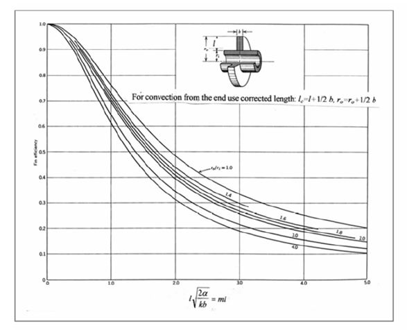
| Finned tubes | Radial (disc) fins (use fin efficiency diagram)
Spiral wound fins can be treated as radial fins |
| Fin height | See table, fins cannot touch or encroach on neighbouring tube/fins |
| Fin thickness | Various thicknesses available (see tables) |
| Fin material | Can be different to that of tube, see tables of materials and costs |
| Fin spacing | Use a recommended fin spacing (fins/m) with a minimum allowable gap
of 3 x fin thickness |
Design notes
In the construction of a heat exchanger the cost of the number of tubes is more expensive that the length of tubes as the drilling of holes and the welding of the tubes into tube plates is costly.
The use of serpentine tubes could be considered, the radius of turn being determined by the fin height chosen.
Data sets
Fin Efficiency diagram for Radial Fins
(Spiral wound fins can be considered as disc, radial fins)
Suggested Heat Transfer Correlations
Dittus-Boelter
𝑁𝑢𝑑 = 0.023 𝑅𝑒0.8 𝑃𝑟𝑛
For Re > 2300 inside tubes/channels
For Re < 2300 (laminar flow)
𝑁𝑢 = 4.36
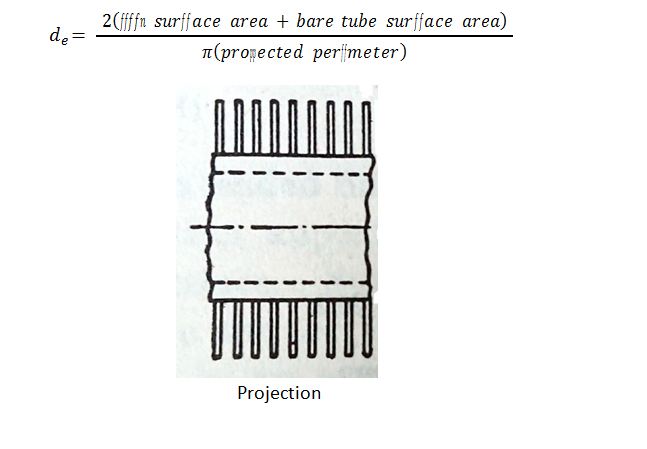
Hydraulic Diameter of a Radially Finned Tube
For a plain cylinder in cross flow.
𝑁𝑢𝑑 = 𝐶 𝑅𝑒𝑚 𝑃𝑟1�3
| Red | C | m |
| 0.4 – 4 | 0.989 | 0.330 |
| 4 – 40 | 0.911 | 0.385 |
| 40 – 4000 | 0.683 | 0.466 |
| 4000 – 40 000 | 0.193 | 0.618 |
| 40 000 – 400 000 | 0.027 | 0.805 |
Available Tubes and fin sizes
(Fins are made of strips of metal of width = fin height and thickness = fin thickness)
| Material | Thermal Conductivity
W m-1 K-1 |
Density kg m-3 | Relative cost Per m3 |
| ++ HIGH TEMP PIPE (430oC) ++
ASTM A106 Gr A seamless (P235GH) |
|||
| 51.00 | 7,850.00 | 3.00 | |
| +++ LOW TEMP ENVIRONMENT PIPE +++
ASTM A333 Gr 1 |
|||
| 50.00 | 7,800.00 | 1.00 | |
| +++ SEAMLESS CARBON TUBE +++
ASTM A179 (seamless, low carbon) |
|||
| 51.90 | 7,858.00 | 2.00 | |
| +++ COPPER TUBE +++
BS EN 12451 R250 (Half Hard) seamless |
|||
| 391.20 | 8,920.00 | 5.00 | |
| +++ ALUMINIUM TUBE +++
ASTM B241 Aluminium (seamless) T6 |
|||
| 161.00 | 2,726.00 | 6.00 | |
| +++Seamless S/STEELS TUBE+++
SS 304 ASTM A213/A213M (Seamless) |
|||
| 15.90 | 7,889.27 | 4.00 |
| Tubes | Fins | ||||
| NB | OD | wall
thickness |
Fin
Height |
Fin
Height |
|
| inches | mm | mm | inches | mm | |
| 1/8 | 10.29 | 1.73 | 1/4 | 6.350 | |
| 1/4 | 13.72 | 2.24 | 3/8 | 9.525 | |
| 3/8 | 17.15 | 2.31 | 1/2 | 12.700 | |
| 1/2 | 21.34 | 2.77 | 9/16 | 14.288 | |
| 3/4 | 26.67 | 2.87 | 5/8 | 15.875 | |
| 1 | 33.4 | 3.38 | 3/4 | 19.050 | |
| 1 1/4 | 42.16 | 3.56 | 22 | ||
| 1 1/2 | 48.26 | 3.68 | 1 | 25.400 | |
| 2 | 60.33 | 3.91 | 1 1/2 | 38.100 | |
| 2 1/2 | 73.03 | 5.16 | 2 | 50.800 | |
| 3 | 88.9 | 5.49 | |||
Available fin thicknesses (m)
0.00035, 0.0004, 0.0005, 0.0006, 0.0007, 0.0008, 0.0009, 0.001, 0.0011, 0.0012, 0.00127,
0.0015, 0.00175, 0.002
Recommended Fins per m
50, 75, 90, 100, 118, 157, 197, 236, 250, 276, 315, 354, 394, 433, 472, 512
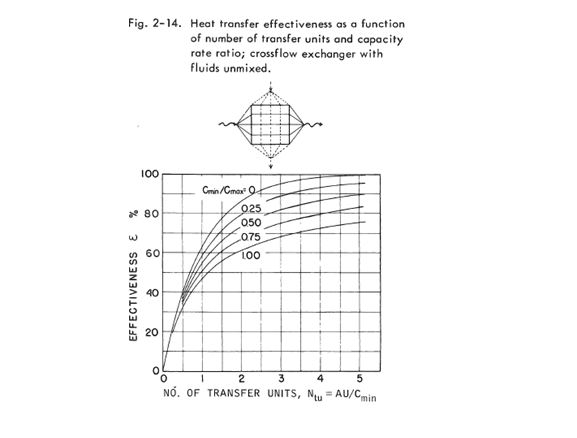
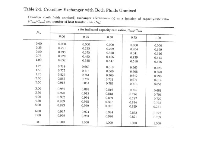
Kays and London table for both fluids unmixed
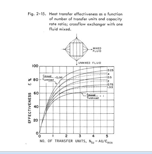
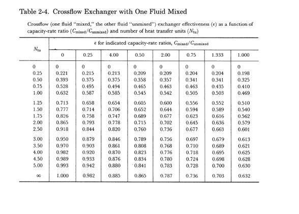
Kays and London table for on fluid mixed, the other unmixed
Properties of Fluids
Shell Thermia-B-HTF
| Temperature | Density | Specific Heat
Capacity |
Thermal
Conductivity |
Viscosity |
| 0 | 876 | 1.809 | 0.136 | 253.73 |
| 20 | 864 | 1.882 | 0.134 | 64.430 |
| 40 | 850 | 1.954 | 0.133 | 25.53 |
| 100 | 811 | 2.173 | 0.130 | 4.06 |
| 150 | 778 | 2.360 | 0.128 | 1.7 |
| 200 | 746 | 2.638 | 0.121 | 0.954 |
| 250 | 713 | 2.720 | 0.118 | 0.607 |
| oC | kg m-3 | kJ kg-1 K-1 | W m-1 K-1 | x 10-3 kg m s-1 |
Dry Air
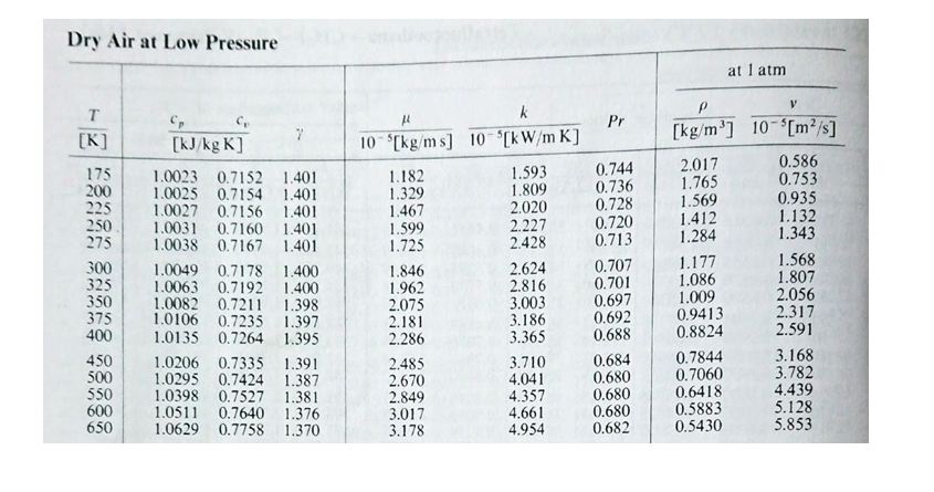
For REF…USE: #getanswers2001853